 International
 Singapore
 Malaysia
 Thailand
 Vietnam
Your shopping cart is empty!

CONTENTS |
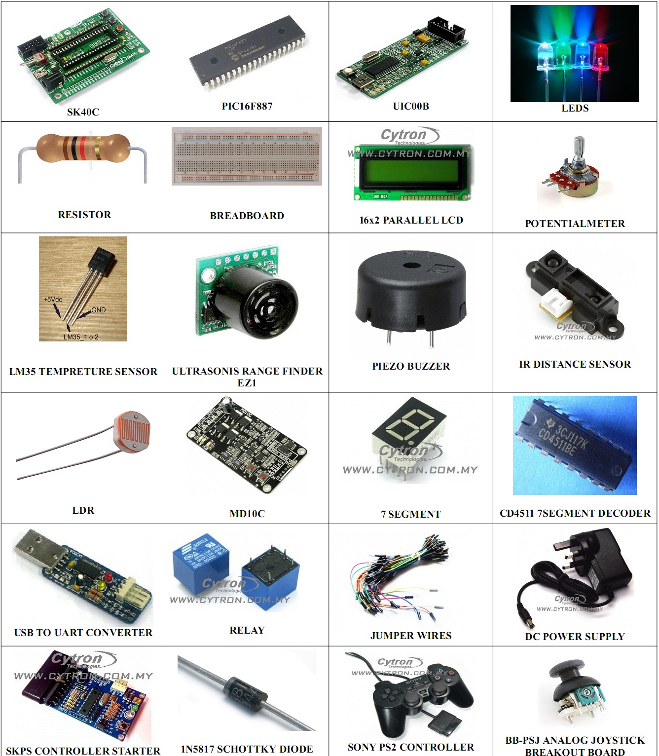
COMPONENTS REQUIRED
WHAT’S EXACTLY INSIDE SK40C
BOARD OVERVIEW
SK40C, a enhanced version of SK40B which can support 40 pins PIC16F and PIC18F. This board comes with basic element suitable for both hobbyist and experts. This kit is designed to offer:
- Industrial grade PCB
- Compact, powerful, flexible and robust start-up platform
- Save development and soldering time
- No extra components required for the PIC to function
- All 33 I/O pins are nicely labeled to avoid miss-connection by users
- Connector for UIC00A/UIC00B (low cost USB ICSP PIC Programmer) – simple and fast method to load program
- Fully compatible with SK40B
- No more frustration unplugging PIC for re-programming
- Perfect fit for 40 pins PIC16F and PIC18F
- With UIC00B, program can be loaded in less than 5 seconds
- More convenient to use and it is smaller than SK40B.
- Maximum current is 0.5A.
- Dimension: 85mm x 55mm
SK40C comes with additional features:
- 2 x Programmable switch
- 2 x LED indicator
- Turn pin for crystal. User may use others crystal provided.
- LCD display (optional)
- UART communication
- USB on board.
- And all the necessities to eliminate users difficulty in using PIC.
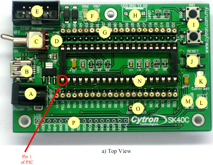
A – DC power adapter socket for user to plug in DC adapter. The input voltage should be in the range of 7 – 15V.
B – USB connector for communication between SK40C and a host controller. This function is only valid for certain models of PIC microcontroller. Please refer to SK40C User Manual. The power LED will light ON when USB cable is connected.
C – Toggle switch to ON/OFF the power supply from DC adapter.
D – Power indicator LED. It will light ON as long as the input power is connected correctly.
E – 2×5 box header for UIC00A & UIC00B, USB ISCP Programmer.
F – 2 LEDs (connected to RB6 and RB7) as active High output for PIC MCU. These LEDs are controllable from PIC MCU.
G – Consist of several line of header pin and turn pin. Header pin provide connector for user to solder SK40C to prototype board and use the I/O of PIC MCU. It is fully compatible with SK40B. Turn pin offers a simple way to check voltage with a multimeter probe. 40 pins of PIC MCU except OSC (connected to crystal) are extended out to these pins. There is an extra pin on top of MCLR which is labeled as Vin, is connected to the input power.
H – 2x Push Button connected to RB0 and RB1 of PIC MCU. This is extra input button for user. It can be programmed as input switch.
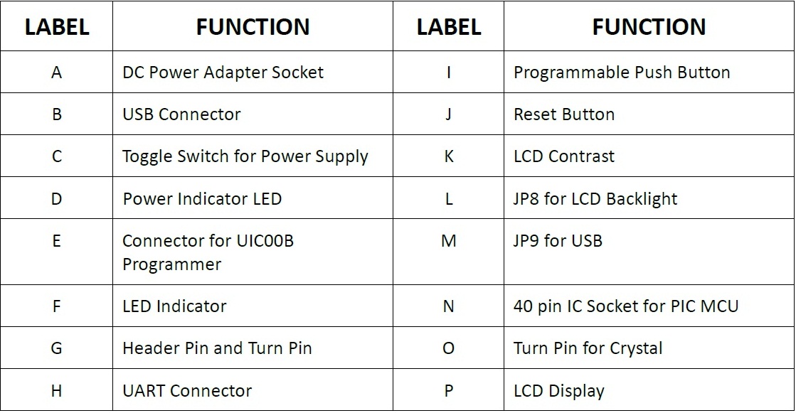
I – Reserved for UART communication. Tx and Rx pin of SK40C are connected to RC6 and RC7 respectively. Ensure PIC user have the correct UART pin (RC6 and RC7).
J – Reset button for PIC MCU.
K – 5K trimmer for LCD contrast.
L – JP8 for LCD backlight. LCD Display will have backlight if this pin is shorted.
M – JP9 is for USB. Connect this pin to use USB port.
N – 40 pin IC socket for user to plug in any 40 pin PIC MCU(8Bit). It can be either 16F or 18F PIC. Of course the IC package should be PDIP. Please ensure the first pin is at the top side.
O – Turn pins is provided for crystal. 20MHz is the default crystal provided in SK40C. The 20MHz crystal can be replace with other value. Just remove and plug a new crystal on the turn pin. No soldering required.
P – Reserved for 2 x 16 LCD. User may solder the LCD here if it is needed.
2 X 16 Parallel LCD Connection Pin (Label P)

Turn Pin For Crystal (Label O)

Push Button Pin (Label I)

UART PIN (Label H)

GETTING STARTED
You can choose either to use MPLAB X IDE or MPLAB IDE to edit, compile and load your program. We would recommend MPLAB X IDE as it has more features.
For MPLAB X IDE, you can refer to Getting Started with MPLAB X IDE.
For MPLAB IDE, you can refer to Getting Started with MPLAB IDE.
HARDWARE SETUP

To start, plug the PIC16F887 into the socket that have been provided. Make sure the PIC MCU is correctly placed in the SK40C board. The PIN 1 is just next to the little half moon shape or circle.


Next, connect the A-type USB to the PC as shown below.

After that, plug in the USB(mini) to UIC00B. The power supply indication, green LED will light ON.

Finally, connect one side of the programming cable to the box header of UIC00B and the other side to the box header of SK40C(Target device) to upload the code. Make sure that external power(DC adapter or battery) for SK40C is provided when uploading.

I/O PORT
The input and ouput(I/O) of the PIC MCU can be accessed through few methods such as using jumper wire, plugging on to a breadboard or soldering it on adonut board/strip board.


PROJECT 0: MY 1ST PIC PROJECT, LOAD A SIMPLE LED BLINK

In this project, we are going to do a simple LEDs blinking using the LEDs on SK40C. Here, we are using both of the LEDs and blink it like a police car. Besides learning electronic parts, you will also learn about some coding in C. More…
PROJECT 1: LED BLINKING: LED CHASER

In project 1, you are about to experience how to program a LED chaser where we can increase the running speed by just pushing a single button. While releasing it, the speed will slowly turn back to normal. Here, we are going to use a total of 6 LEDs and will connect it with a current limiting resistor before plugging into the I/O port. More..
PROJECT 2:“HELLO WORLD” WITH PARALLEL LCD

For project 2, we will show you how to interface the SK40C board will a parallel 16×2 LCD display. The connection are simple and the coding are easy to learn. We are going to display the “Hello World” on the LCD display by just adding a library that has been done for you. More..
PROJECT 3: DIGITAL INPUT: PUSH BUTTON

For this project, we will discover how to manage a digital input signal. As we know that digital signal is either HIGH (1) or LOW (0). But for different integrated circuit such as PIC MCU, we need to define at the beginning of the code that the port used are either input or output; digital signal or analog signal. More..
PROJECT 4: ANALOG SENSOR: POTENTIALMETER & BB-PSJ

In this part, we are going to discuss about how to write the Analog to Digital Converter code which has become the most popular question among the students. We are going to use PIC16F887 with have contain of 10-bits binary result and a potential-meter to adjust the voltage different and display it in the LCD display. More..
PROJECT 5: ANALOG SENSOR: TEMPERATURE USING LM35

Nowadays, there are many type of temperature sensor is come with different output form and also the temperature range such as thermocouple, thermistor, infrared, RTD. In here, we pick LM35 as our temperature sensor due to it have a linear output and also suitable for normal use like weather temperature measuring. More..
PROJECT 6: ANALOG SENSOR: RANGE USING ULTRASONIC RANGE FINDER

There are many sensor to measure a range such as using Ultrasonic, Infrared and more. In here, we are going to experience how to measure a range using Maxbotic Maxsonar-EZ1 ultrasonic range finder which it will give the output value in inch. More..
PROJECT 7: ANALOG SENSOR: RANGE USING ANALOG DISTANCE SENSOR

Analog distance sensor which have a function that same as the Ultrasonic sensor which is use to measure range. But for this sensor, the output value are in centimeter(cm) and also the output are only given an analog value. To get the result, an mathematics formula are required to apply into our C-code for calculation. More..
PROJECT 8: PIEZO BUZZER: MELODY – BIRTHDAY SONG

Piezo buzzer, generally use as a sensor and actuator which are use to measure force, pressure , tools for positioning object and etc. As for this project, we are going to use it to generate a melody by applying PWM frequency to it. More..
PROJECT 9: ANALOG SENSOR: LIGHT DETECTION USING LDR

A photoresistor or light dependent resistor (LDR) is a resistor whose resistance decreases with increasing incident light intensity. It can also be referred to as a photoconductor. In here, we going to do a simple connection of LDR and display the ADC and Voltage value on LCD. More..
PROJECT 10: DRIVING DC BRUSH MOTOR WITH MD10C

MD10C is an enhanced version of the MD10B which is designed to drive high current brushed DC motor up to 10A continuously. It offers several enhancements over the MD10B such as support for both locked-antiphase and sign-magnitude PWM signal as well as using full solid state components which result in faster response time and eliminate the wear and tear of the mechanical relay. More..
PROJECT 11: 7 SEGMENT DISPLAY WITH DIRECT I/O

Nowadays, 7 segment has become the most popular display unit on market because it is cheap, easy to program and small. On market, we can found that there was 2 types of 7 segment which is common anode and common cathode. In this project, we are going to use 7 segment with common cathode and directly interface to microcontroller. More..
PROJECT 12: 7 SEGMENT DISPLAY WITH CD4511 ENCODER

Besides on directly connected 7 segment with direct I/O port from microcontroller, we can also use the CD4511 (7 segment encoder) to help on decreasing the microcontroller I/O port and only required to send the binary data. More..
PROJECT 13: UART TO COMPUTER

Universal Asynchronous Receive/Transmit (UART) has becoming a popular item on sending and receiving data in the fast way. In here, we are going to experience on how to use UC00A to communicate with our computer/PC and SK40C. More..
PROJECT 14: INTERFACE WITH RELAY

Relay have become a common use electronic component which operate as an switching device by simply apply voltage to ON and OFF it. For this project, we will discover a simple relay connected with an LED to show what is the basic function and connection. More..
PROJECT 15:INTERFACE WITH SKPS

Play Station 2 (PS2) controller is relatively easy to obtain from any game store and it offers good human manual input for control system. More and more developers are looking into applying existing PS2 controller to control particular system. In here, we going to explore on how to interface PS2 controller with SK40C through SKPS controller starter kit. More..
PROJECT 16: DRIVING TWO DC BRUSH MOTOR WITH MD10C BY USING SKPS

In this project, we will learn about how to drive two DC geared motor with MD10C by using SKPS. Thus, we will treat these two motors as the left wheel motor and right wheel motor. Therefore, we will use PS2 controller to control two DC motors in various type of movements such as move forward, move backward, rotate to left, rotate to right. In addition, we will use joystick to control these two motors in different movement with constant speed and variable speed. Meanwhile, we will use PIC16F887 in this tutorial for SK40C with LCD 2×16 to display some important messages when certain button of PS2 controller was pressed. In addition, the sample code that used for PIC16F877A will also be attached at the end of this tutorial. More..
PROJECT 17: INTERFACE WITH 4X4 KEYPAD

In order for the micro-ocontroller to determine which button is pressed, it first needs to pull each of the four column either low or high one at a time, and then poll the states of the four rows. Depending on the states of the rows, the micro controller can tell which button is pressed. In this tutorial, you will learn on how to display the character on LCD by pressing the 4×4 keypad button. More..
ATTACHMENT:
1. User Manual.pdf
2. SK40C+PIC16F887 coding
3. SK40C Cheat Sheet