 International
 Singapore
 Malaysia
 Thailand
 Vietnam
Your shopping cart is empty!

Good! You are here because you wanted to use Arduino. 1st thing 1st, you will need the necessary tools to get started, and this guide is meant for Arduino Fio
- Arduino Main Board (There are plenty of Arduino main boards in the market)
- USB cable and UC00A Rev2.0 for loading program. Some Arduino Main board comes with the USB cable, but some not :)
- 2 units of XBee Series 1 module (for wireless program loading)
- SKXBee w/o module
- X-CTU software
- Arduino IDE
- Breadboard (Optional)
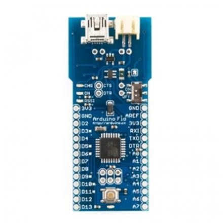
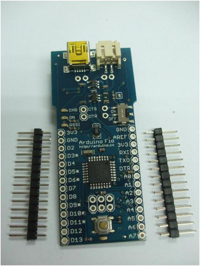
ARDUINO MAIN BOARD – FIO
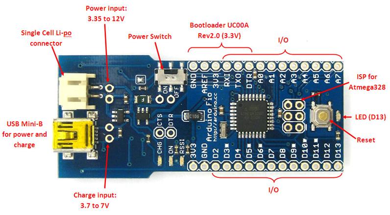
Currently, there are > 10 types of Arduino main boards in the market including 3rd party, compatible versions, etc. We will not cover all. I will focus on Arduino – Fio. Other types of Arduino main boards have the basic operation, with a little tuning and exploring, I am sure you can get the hang of it. So get the Arduino Fio. Please take note, there are several methods to load programs into Fio, wired or wireless, I will show you the wired method and continue with wireless. Depending on which method you prefer, get the necessary hardware and software. BTW, Fio is 3.3VDC operated, do take note of that. If you have any problems, welcome to discuss it in our technical forum. You can also refer to:
- Getting Started with Arduino – UNO
- Getting Started with Arduino – Leonardo
- Getting Started with Arduino Mega ADK
- Getting Started with Arduino – BBFuino
- Getting Started with Arduino – PRO Mini
Loading Program via Wired method
There are 2 methods to load program/sketch into Arduino Fio. I will be showing the wired method first. Please get the:
- UC00A Rev2.0 – USB to UART converter
- USB Mini-B cable
UC00A REV2.0 OR COMPATIBLE DEVICE
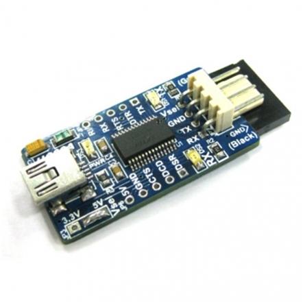
Arduino Fio is an Arduino controller without the programming device installed on it. This is to reduce the cost of Fio because the programming device can be reused for other Fio and Arduino controllers, and is quite common. This is similar to BBFuino and PRO Mini. Therefore, you need to get a tool to load the program, we have that tool, the UC00A Rev2.0. Basically, it is a USB to UART bridge. Arduino uses a serial bootloader to load the program into the target Arduino board. UC00A Rev2.0 comes with the socket ready for program loading J
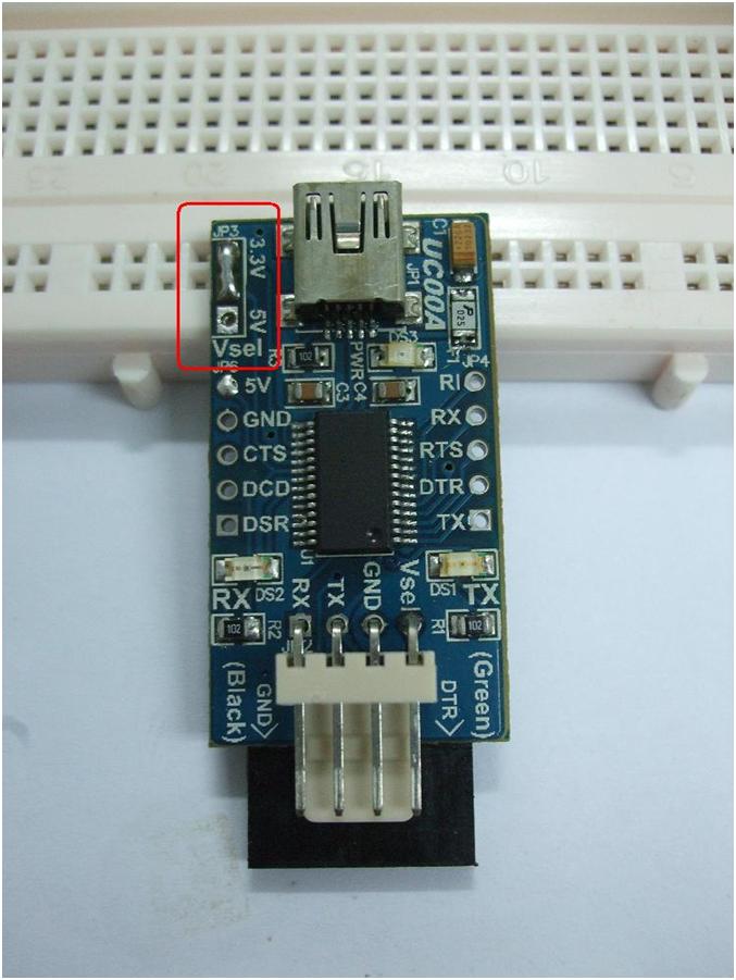
But, there are minor changes you need to make on UC00A Rev2.0 to be able to load the program into Fio. UC00A Rev2.0 default TTL and power is 5V, while Fio is operating at 3.3V. Connecting the UC00A without modification will likely kill the voltage regulator on Fio. I never try it J. To make sure it works fine, please change it to 3.3V. Simple, just de-solder the pad at the left top corner of UC00A where it is labeled “Vsel”, default is 5V. De-solder the 2 pads. Connect the center pad to 3.3V. DO NOT solder all 3 pads together, only 2 pads. BTW, you can utilize 3 pin header and mini jumper to make it flexible J
USB CABLE
UC00A Rev2.0 will require a USB mini B cable. The cable is for connecting UC00A Rev2.0 to a computer for loading programs to Arduino Fio, in some cases for power, and also for serial communication. BTW, USB mini B cable is commonly used on UIC00B, GPS, SKXBee Rev2.0, and Motorola phones. Try using that USB cable if you have one.
ARDUINO IDE
Arduino IDE is the software tool needed to write sketch (code), and load it into the Arduino main board. Please go to the Arduino website at arduino.cc, under Download, please download the corresponding IDE base on your Operating system (Windows, Mac OS X, Linux). This is the location to download the latest version of Arduino IDE.
Unzip the downloaded file.
ARDUINO MAIN BOARD TO COMPUTER (WIRED)
Now, since this is your 1st time, it is always going to be painful, right? BTW, I will be showing the steps using Windows XP only :) Connect one end of the Mini B type USB cable to UC00A Rev2.0 and the other end to the computer/laptop USB port. The UC00A Rev2.0 will automatically use the power from the USB to start up. The green LED (ON) on UC00A should be ON. 1st time user, you will need to install the USB driver for UC00A Rev2.0. You should also hear a sound from the computer and a little popup message box at the bottom right corner of the screen saying Found New Hardware…..FT232…. you will need to install the driver
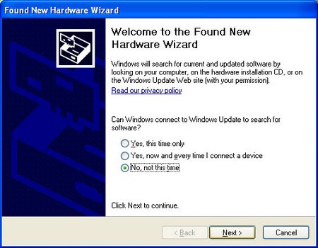
The Found New Hardware Wizard will appear please select No, not this time and click Next >
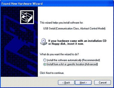
Select Install from a list of specific location (Advanced) on the next screen. Click Next >
On the next screen, make sure you select Include this location and browse to the Arduino IDE folder that you just downloaded and unzipped. Select the drivers -> FTDI USB Drivers folder, and click OK.
The wizard should start searching for necessary files and install the driver, you should get this window, and click Finish.
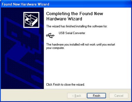
You might get this warning message pop up, just click Continue Anyway.
And it should install successfully and you will get this:

you might need to reboot/restart the computer to get the driver working properly, don’t worry, it’s only one-time work! After the computer reboot, please make sure the UC00A Rev2.0 is plugged into the computer through the USB cable. The green LED is ON. We would like to know which COM number is the UC00A Rev2.0 connected to. Go to the Device Manager (from the Start Menu, select Settings -> Control Panel. Double Click on System and select Hardware tab. Then click on Device Manager).
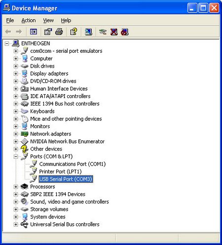
Look for an entry under Ports (COM & LPT) that shows USB Serial Port (COM "X") where X is a decimal number from 1 to 100. Seriously, I have seen COM250 before! Anyway, the X can be any number and it should be a unique number and we need it in Arduino IDE later. So in this case, the COM number is 3. You will need to select the correct COM number to load the program/sketch into Arduino Fio later. If you don’t see any USB Serial Port, unplug the USB cable and plug it in again. The driver for UC00A Rev2.0 is installed. Now connect the UC00A Rev2.0 to Arduino Fio, but where?
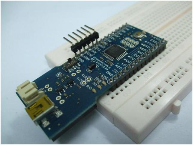
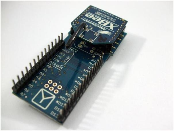
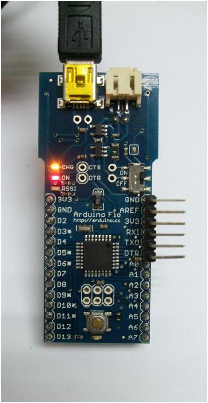
Arduino Fio comes without any header pin and socket for UC00A Rev2.0 to connect to, you will need to solder it yourself. I will be soldering the header pins for the breadboard and adding an additional right-angle 6-way header for program loading via UC00A. Prepare the header pins needed; it should be 14-way each.
Solder it, and when it is done, add a 6-way right angle header to the right top header pin as shown, from GND to DTR pin.
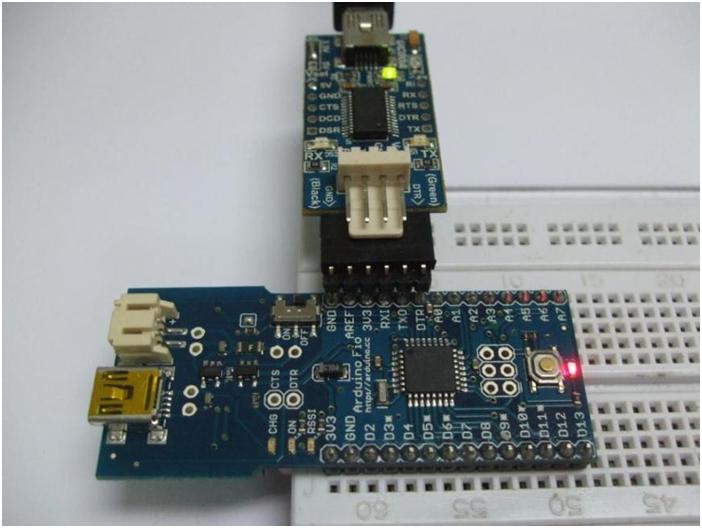
Now, connect the socket of UC00A Rev2.0 (3.3V) to the Arduino Fio 6-way bootloader pin which you have just soldered. Remember, there is polarity for this connection. Make sure the GND (Black) on UC00A is connected to the GND pin on Fio, and the DTR (Green) is connected to the DTR pin on Fio. Double-confirm before you plug in.
Once the UC00A is connected to the computer (via USB cable) and connected to Arduino Fio properly, the Red LED (very small LED near the reset button) on Fio will Blink, this indicates Fio is powered and running program, preloaded program. Arduino Fio is preloaded with a bootloader. Now is the time we load 1st sample program/sketch.
Good, the pain is over for loading the program using the wired method :) You can jump to Hello World – Arduino. I will be showing the preparation needed for wireless program loading.
Loading Program via Wireless method
Hardware and software needed for wireless program loading to Arduino Fio:
- 1 unit of SKXBee Rev1.0 without XBee module
- 2 units of XBee series 1 module
- 1 unit of USB Mini-B Cable, to power Arduino Fio
- X-CTU software
OR
- 1 unit of SKXBee Rev2.0 without XBee module (By the time I write this, the SKXBee Rev2.0 is yet to be launched)
- 2 units of XBee series 1 module
- 2 units of USB Mini-B Cable, one for SKXBee Rev2.0 and another to power Arduino Fio
- X-CTU software
There are many options, the main tools we need are a pair of XBee series 1 module (I have yet to try series 2, but it should work), power to Arduino Fio, and SKXBee to plug XBee into a computer for program loading, wirelessly. I will be using option 2 because I have SKXBee Rev2.0 J, and I will also show the modification needed for SKXBee Rev1.0
SKXBEE REV2.0
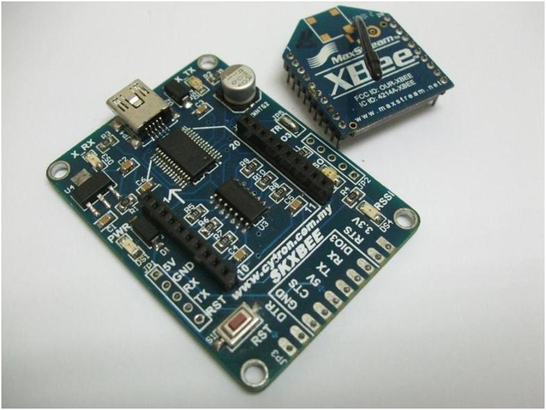
As highlighted earlier, Arduino Fio is an Arduino controller without the programming device installed on it to reduce the cost of Fio. In the wired method, UC00A Rev2.0 provides the loading path. In the wireless method, XBee provides that. If you notice, at the back of Arduino Fio, there is a pair of 10-pin sockets (2mm pitch to pitch). It is meant for the XBee module. Fio is designed to load programs wirelessly via XBee :). By now you should have guessed, 1 XBee module on Fio, and another XBee module should be connected to a computer to load the sketch. Yup, you are right. The XBee module connected to the computer will need SKXBee. Both the XBee series 1 module need to be configured using X-CTU software before you can use it for wireless program loading.
Download and install the X-CTU, is quite straightforward.
USB CABLE
SKXBee Rev2.0 will require a USB mini B cable. The cable is for connecting SKXBee Rev2.0 to a computer for communication with the XBee module, and also to power the SKXBee and XBee modules on it. BTW, the USB mini B cable is commonly used on UIC00B, GPS, SKXBee Rev2.0, and Motorola phones. Try using the USB cable if you have one. Another USB mini-B cable you going to need is for powering Arduino Fio in the wireless method.
If you are using SKXBee Rev1.0, it comes with a USB B Cable. Just use it and if you don’t have one, try to get it from your USB printer, B type USB is commonly used on printer J
Now the installation of the driver, SKXBee has a USB to UART chip and is the same as the UC00A Rev2.0 chip. We will utilize the same steps for installing the driver, please refer to earlier steps here. For those that have been using SKXBee or UC00A, you can skip this part.
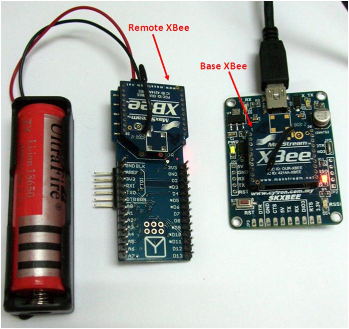
By now, you should get your SKXBee working with the computer (driver installed properly), we need to configure both the XBee modules. Each XBee module has a different role, so I will label them as “Remote” with R, and “Base” with B.
- Remote XBee is referring to the XBee module which will be connected to Fio.
- Base XBee is the XBee module plug on SKXBee connected to the computer during program loading.
Since you have only one SKXBee, you will need to swap the XBee module for configuration. Let’s start with the Remote XBee module.
Remote XBee module
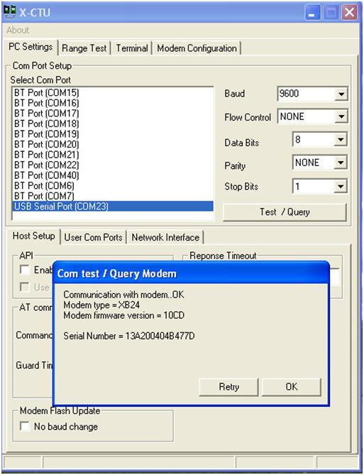
To avoid any confusion, label an XBee module with “R” to indicate the Remote XBee. Plug into the SKXBee, and connect the SKXBee to the computer via a USB cable. Open X-CTU. Select the correct COM port. Normally is labeled as USB Serial Port (COMX) The X can be any number, it is the COM number of the SKXBee USB to UART chip, which is COM23. Set the:
- Baud to 9600
- Flow Control to None
- Data bits to 8
- Parity to None
- Stop bits to 1
You can verify the working and COM number by pressing the Test/Query button under Stop Bits. If the settings and XBee are working, after 1 to 2 seconds, you should see this:
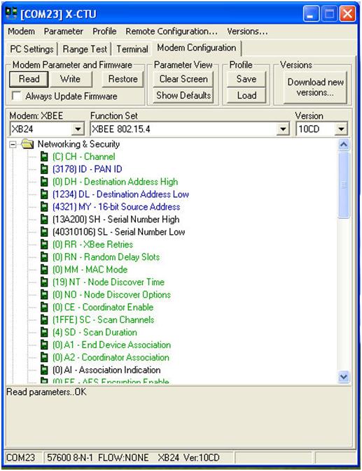
If you have a fail message, most likely is the baud rate. Try changing the baud rate and test again. If it is working, click the Modem Configuration tab on X-CTU, and click the Read button, and X-CTU will read the current configuration (parameters) on the XBee. Now change the settings accordingly:
- PAN ID: 3178. Under Networking & Security. This is Personal Area Network ID. We can utilize this ID to provide better security and immunity to interference between other XBee. The Base XBee will need to have the same PAN ID. You can put any Hexadecimal number, I will use 3178, the last four digit number of our office number.
- DL – Destination Address Low: 1234. Under Networking & Security. Destination low address. The factory default is 0. Change it to 1234, this will also be the Base XBee’s MY address.
- MY – 16-bit Source Address: 4321. Under Networking & Security. MY address. The factory default is 0. Change it to 4321, this will also be the Base XBee’s DL address. DL and MY will be the pairing address of both XBee modules.
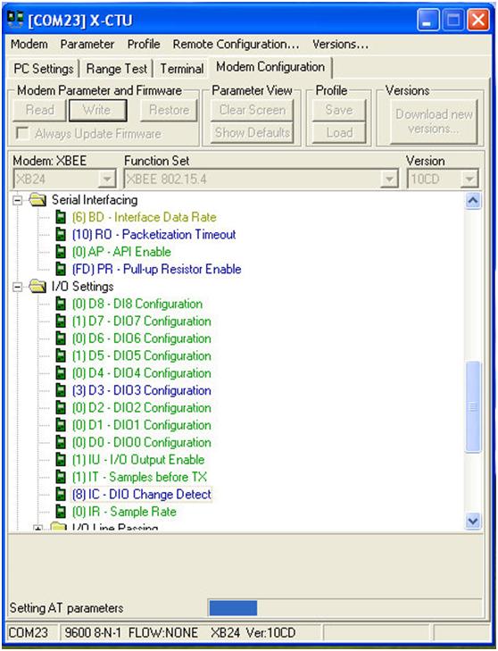
- Interface Data Rate: 6 – 57600. Under Serial Interfacing. This is the baud rate of the UART interface between the computer and the XBee module. Since Fio is using 57600 baud, XBee needs to be configured to this speed.
- Packetization Timeout: 10. Under Serial Interfacing. This value determines how long the XBee waits before sending the characters over to another XBee wirelessly. We’re doing some ‘bulk transfer’ when sending 10K programs over, so just try 10.
- D3 – DIO3 Configuration: 5 – DO HIGH. Under I/O Settings. This is to make the D3 pin on XBee (pin 17) as output and the default is HIGH. This is used to reset Arduino Fio during bootloader (check the schematic of Fio). It will be paired with Base XBee’s DIO3 pin. When DIO3 from Base XBee detects changes, Remote XBee’s D3 will reset the Fio further and enter the bootloader.
- UI – I/O Output Enable: 0 – Disabled. Under I/O Settings. This will prevent the changes to be notified through UART, and instead will change the output pin only.
- A – I/O Input Address: FFFF. Under I/O Line Passing. Configure this Remote XBee to receive the I/O changes detection from a pairing XBee, FFFF will work fine because it will detect all XBee I/O changes.
Now, click the Write button to load this new setting into Remote XBee on SKXBee. Once it is done, the new baud for Remote XBee is 57600bps. BTW, I am using the 10CD version of firmware for both my XBee module, you should at least use this version or later.
The new setting for Remote XBee would be:
- PAN ID = 3178
- DL = 1234
- MY = 4321
- Interface Data Rate = 57600bps
- Packetization Timeout = 10
- D3 – DIO3 Configuration = 5 – DO HIGH
- UI – I/O Output Enable = 0 – Disabled
- A – I/O Input Address = FFFF
BTW, if you want to read the configuration from the Remote XBee again, you need to change the X-CTU’s baud rate to 57600 under the PC Settings tab.
Close the X-CTU, and disconnect the SKXBee from the USB cable. Unplug the Remote XBee module from SKXBee, plug it into Fio (the back), mind the orientation, DO NOT plug wrongly, you will damage the XBee module.
Base XBee module
Take the other XBee module, and label it as “B”. Plug into the SKXBee, and connect the SKXBee to the computer via USB cable. Open X-CTU again. Select the correct COM port, it should be the same as the earlier selection because you are using the same SKXBee and USB port. Set the:
- Baud to 9600
- Flow Control to None
- Data bits to 8
- Parity to None
- Stop bits to 1
You can verify the working and COM number by pressing the Test/Query button under Stop Bits. Same as what you did for Remote XBee just now.
If you have a fail message, most likely is due to the wrong baud rate. Try changing the baud rate and test again. If it is working, click the Modem Configuration tab on X-CTU, and click the Read button, and X-CTU will read the current configuration (parameters) on the XBee. Now change the settings accordingly:
- PAN ID: 3178. Under Networking & Security. This ID must be the same as Remote XBee, I am using “3178”, the last four digits of our office number.
- DL – Destination Address Low: 4321. Under Networking & Security. Destination low address. The factory default is 0. Change it to 4321, this is the Remote XBee’s MY address.
- MY – 16-bit Source Address: 1234. Under Networking & Security. MY address. The factory default is 0. Change it to 1234, this is the Remote XBee’s DL address.
- Interface Data Rate: 6 – 57600. Under Serial Interfacing.
- Packetization Timeout: 10.
- D3 – DIO3 Configuration: 3 – DI. Under I/O Settings. This is to make the D3 pin on XBee (pin 17 on XBee) as input. This will be used for DTR from FT232 (also connected to XBee’s DTR) for resetting Fio at the other end. XBee is capable of detecting changes on the I/O pin further transmit to the paired XBee and outputting it.
- IC – DIO Change Detect: 8. Under I/O Settings. Configure this base XBee to monitor the change of DI3. Value 8 is 0000 1000 in binary. Bit-3 set is to configure XBee to monitor pin DIO3 which we set as input just now.
Now, click the Write button to load these new settings into Base XBee on SKXBee. Once it is done, the new baud for Base XBee is 57600bps. Close the X-CTU, we do not need it anymore. Just remember the COM port number, we need it on Arduino IDE later.
The new setting for Base XBee would be:
- PAN ID = 3178
- DL = 4321
- MY = 1234
- Interface Data Rate = 57600bps
- Packetization Timeout = 10
- D3 – DIO3 Configuration = 3 – DI
- IC – DIO Change Detect: 8
You will need to do some modifications on the SKXBee to enable wireless bootloading :)
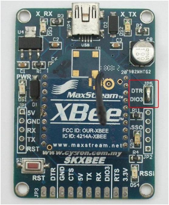
Take the SKXBee Rev2.0, and look carefully, at the right side of the XBee module, there are 2 pads labeled as DTR and DIO3, short it using solder lead.
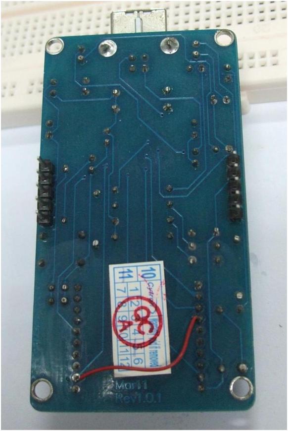
If you are using SKXBee Rev1.0, flip it over; solder a jumper wire to connection pin 9 (DTR) and 17 (DIO3).
Yeah! Is near, don’t worry; this will be one-time work:) Is painful, but is fun when you can load the program wirelessly, trust me! The last thing to do is to power the Arduino Fio. The wired method uses power from UC00A Rev2.0 (from USB), but for the wireless method, there is no UC00A Rev2.0 connected anymore, else it will be no point doing wireless. To power the Fio, there are a few choices. The easiest method, power it from USB. For the sack of demo, you just grab a USB mini B (not from SKXBee) and power it from the computer. The USB mini-B socket of Fio is meant for power only, not for the program. That is the reason why I put 2 units of USB Mini-B cable under the Wireless method.
Or you can use a single-cell Li-po battery to power the Fio. We do not carry the single-cell lipo battery, but we do have a single-cell rechargeable Li-ion battery which has a similar voltage to Li-po. Get the single-cell 18650 battery holder + 18650 Li-ion rechargeable battery, solder some simple connectors, and a 2 pin right angle header to Fio, you will get this, fully remote/mobile Arduino Fio.
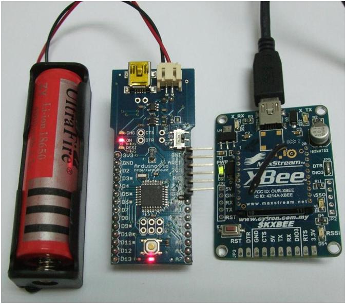
Not to forget, the Remote XBee is should be plugged in at the back of Fio and Base XBee stay with SKXBee and connected to the computer.
Doesn’t matter how you power it, as long as it is powered properly. We are now going to load the program. The ASSO LED on SKXBee will blink when XBee is on it and powered.
Hello World – Arduino
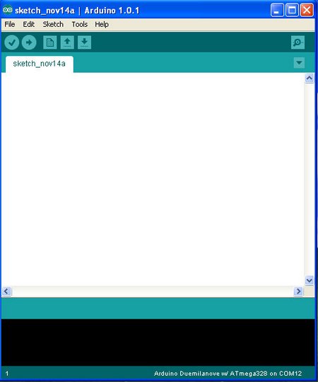
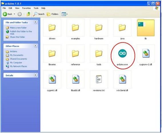
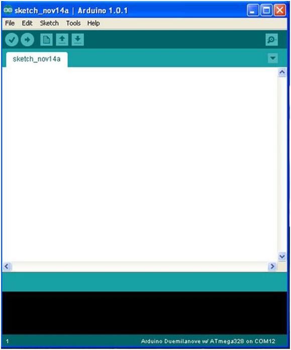
Let’s move to the fun part. For this section, it does not matter whether you use the Wired or Wireless method, the steps are the same. We will do Hello World in Arduino – LED blinking. Open the folder Arduino that you download and unzipped, you should see a file named arduino.exe, double click it, and Arduino IDE will appear, it may take a while to load, ~ 10 seconds. No further installation is needed. Arduino IDE does not require installation.
This is the Arduino IDE:
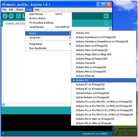
Make sure the UC00A Rev2.0 if you are using the Wired method; SKXBee is connected via USB cable if you are using the Wireless method. Arduino IDE supports many Arduino main boards. We will need to select the correct board and microcontroller. Goto Tools -> Board -> Arduino Fio, click it.
Now, make sure Arduino IDE knows which COM Port the Arduino Fio is connected to. Goto Tools -> Serial Port -> COM?, it depends on the COM number you use. If you are using UC00A Rev2.0, select the COM number which you have checked previously using the device manager. If you are using SKXBee Rev2.0 use back the same PORT number that you choose in X-CTU (X-CTU must be closed). Remember, the number might be different when you use different USB ports or change different UC00A, SKXBee, and different computers. Again, mine is COM23 as I am using SKXBee for the wireless method. Do not follow my COM number, choose yours.
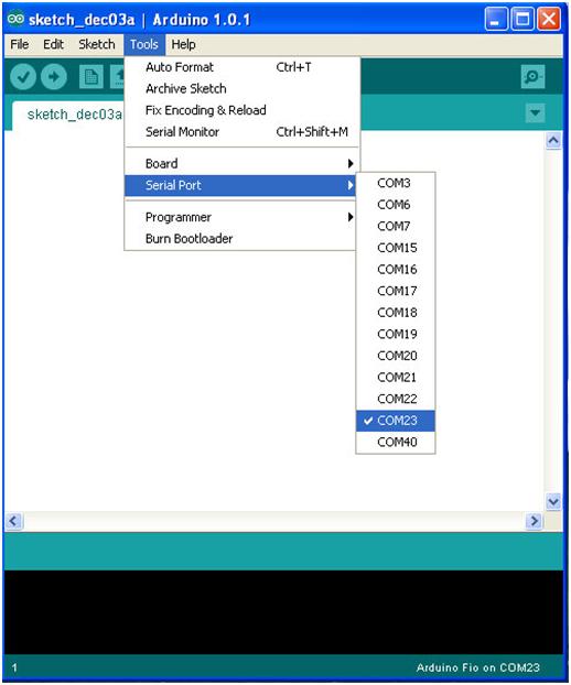
The settings will appear at the bottom right corner of Arduino IDE.
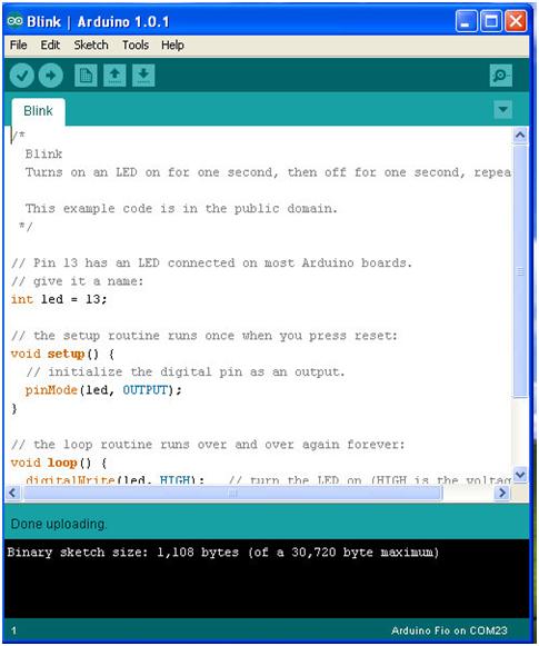
Now, you are ready to load the 1st example code, Blinking :) Goto File -> Examples -> Basic -> Blink, click it. The example sketch/program will appear in a new Arduino IDE window, don’t worry, it’s perfectly normal. You can ignore the empty Arduino IDE that appeared earlier. You can close it or leave it. We will work on the new Arduino IDE with Blink sketch.
You can click the upload icon, Arduino IDE will compile the sketch and upload it into Arduino Fio connected to your computer using UC00A Rev2.0 (Wired method) or SKXBee Rev2.0 (Wireless method), further run the sketch on PRO Mini. You will just have to wait until the message box says Upload Done and look at the Arduino Fio. The Red LED (bottom center, below the Reset button) will blink at a 1-second rate. That LED is connected to D13 of Fio.
So we have just downloaded a new sketch/program into our Fio, congrats! If you notice when the IDE is stating Uploading…. The RSSI LED on Fio and SKXBee will be ON, and the LED of X-RX and X_TX on SKXBee blink indicating the wireless communication started. You have completed the 1st and foremost exercise. To make a little change, I will show you an easy modification. Scroll down the program/sketch, in the loop function. Modify the value from delay(1000) to delay(100), for both the delay. Click on the Upload icon and sit back, waiting until it is done uploading.
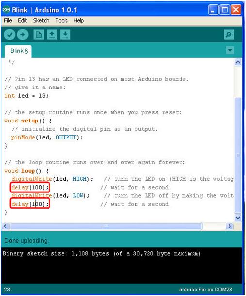
Now, look at the Red LED blinking rate, it has become faster :) You have successfully loaded an example code/sketch and modified it.
Hurray! Now, you can unplug the XBee on Fio and make it fully standalone. Besides using for bootloading, the system can be used for wireless communication, sensor network, remote control, monitor, etc. You can try the other examples, but most will require additional shields or components. Just a reminder, Fio is designed for a compact and intermediate user, and wireless program loading, it is not compatible with shields because of the size and shape, but all the sample code using Arduino IDE can work as long as the interface is correct. We will come out with more tutorials, stay tuned! If you have a problem do feel free to discuss it in our technical forum as we seldom check the comments area on the tutorial site.