 International
 Singapore
 Malaysia
 Thailand
 Vietnam
Your shopping cart is empty!
Last month, I was thinking of doing wireless temperature monitoring at my office. But I do not want to use WiFi or Bluetooth module, because WiFi is expensive and Bluetooth requires establishing a connection. I am out of ideas as the normal RF module is not good to transfer UART data.
Anyway, I was thrilled when our purchasing department give me two low-cost options:
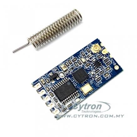
- 433MHz wireless UART module: 1km (kilometers) wireless range. Are you kidding me? Frankly, we have never tested that distance, maybe we will try to verify that some other time. Not to forget, the specification is measured under open space or line of sight. In an urban areas where there are walls, iron, and interference; I would expect a distance of 100 meters or so.
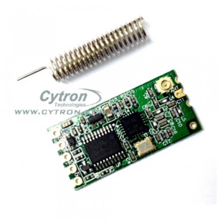
- 434MHz wireless UART module: 100 meters wireless range. Again, this is a super nice wireless range for UART communication.
Please do take note that both these modules are not compatible in terms of wireless communication, they cannot talk to each other as the frequency is different. You must get the same modules for communication.
Nonetheless, both these wireless modules have similarities:
- Come as a transceiver for each module; require at least 2 modules (1 pair) to establish communication.
- The wireless communication frequency band is either 434MHz or 433MHz.
- UART TTL, Half Duplex, supported baud rate from 1200bps to 115200bps, default is 9600bps.
- 100 channels to be configured for security or interference avoidance.
- Configurable in command with AT command.
- Power: +3.3V to +5.5VDC, recommended < 5.0V.
- Low current consumption, depending on operating modes.
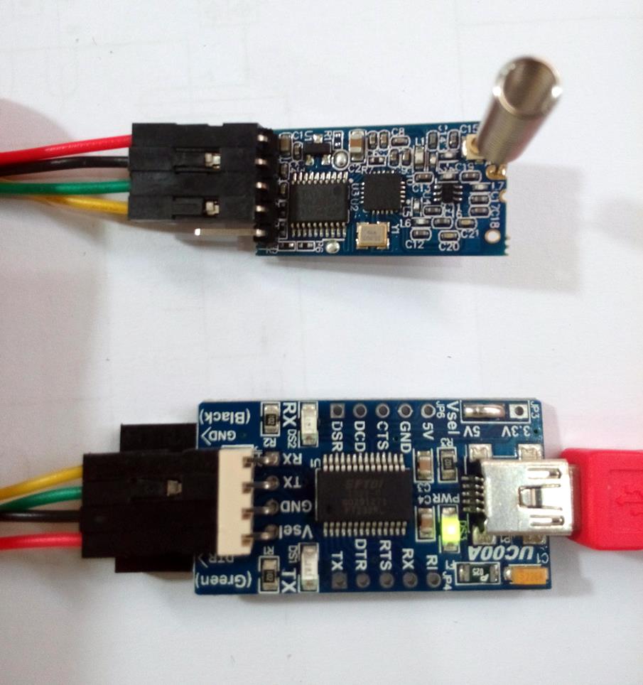
We notice there is a 1K resistor built-in series with the TX and RX pin of 433MHz (1KM) wireless module. This will cause problems when this module is connected to Arduino hardware serial pins (especially pin 0).
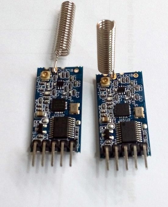
When you get it, the antenna (spring or spiral) requires soldering to the “ANT” pad. Try to fit the hole nicely! I soldered it in two different methods :) Not to forget, you will need to get yourself a header pin to extend the UART and power pin. I am choosing the right-angle header pin. There is a 40-way header, so you have plenty of extra pins to spare.
HARDWARE REQUIRE:
OK, after you had done solder the antenna to the wireless UART module, let’s prepare the temperature reading and send it to the UART program on Arduino. BTW, I am using a 434MHz (100 meters) module, but you can choose 433MHz (1KM) as it is just the distance and wireless frequency that vary between these two types of modules. Not to forget the 1K series resistor on the 433MHz module. I will show both the connections and examples sketch.
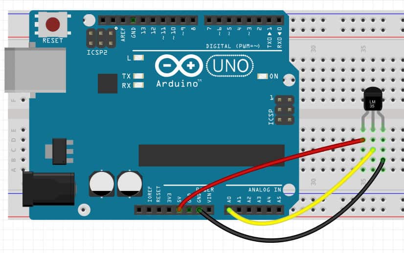
1st thing is always the hardware connection. Connect the LM35 Arduino as shown:
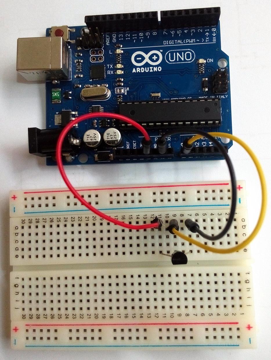
I hope is straightforward. If you like it in Fritzing format, here you go:
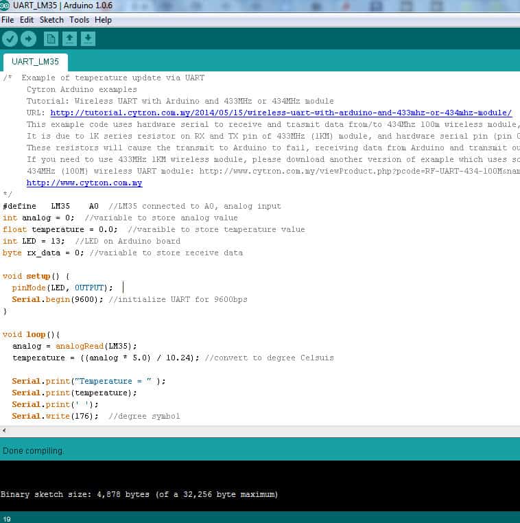
Load this sketch(UART_LM35) into Arduino UNO.
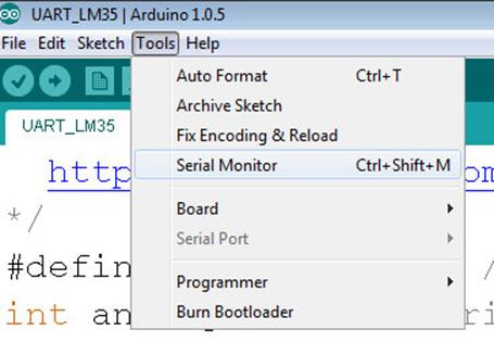
Now open up the serial monitor in Arduino IDE: Tools -> Serial Monitor
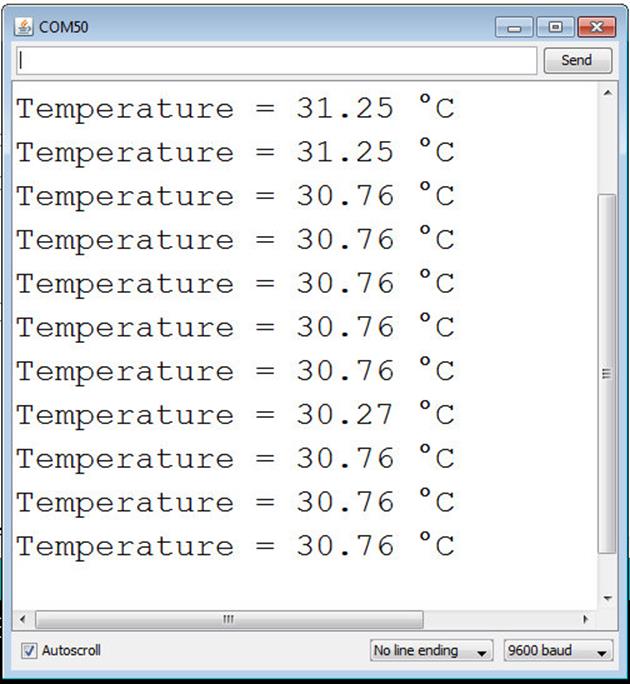
Make sure the Baudrate is 9600 and you should see this:
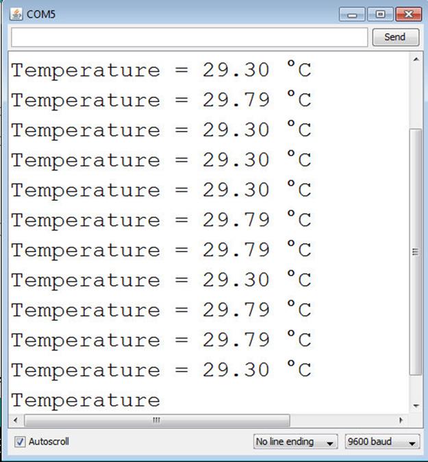
If you type ‘a’ (small letter a) in the top bar of the Serial monitor and send, you will notice the LED on Arduino will light up. Sending ‘A’ (capital letter A) will OFF the LED. Sending another character will not change anything. This is to demonstrate bi-directional communication. The temperature reading is from Arduino to computer while the character ‘a’ or ‘A’ is from computer to Arduino.
Em…. I know that this is UART, is simple! I want wireless. Yes, wireless UART is the same as UART. To develop and make sure the communication is working and you get a proper reading and temperature updates. It seems my office is quite a hot place to work :) Yeah! 29 degree Celsius.
After verify everything is working properly, let’s proceed to wireless. No code modification is necessary if you plan to:
- use the baud of 9600, as the wireless module comes default in 9600 baudrate.
- 434MHz (100 meters) wireless UART module
If you plan to use the 433MHz (1KM) wireless UART module, you will need to do minor modifications to the sketch and also the connection, I will show this later.
We need to set up the wireless module with Arduino and also with a computer. It is different with Bluetooth or WiFi, you do not need to establish a connection by searching or keying in the pairing key :).
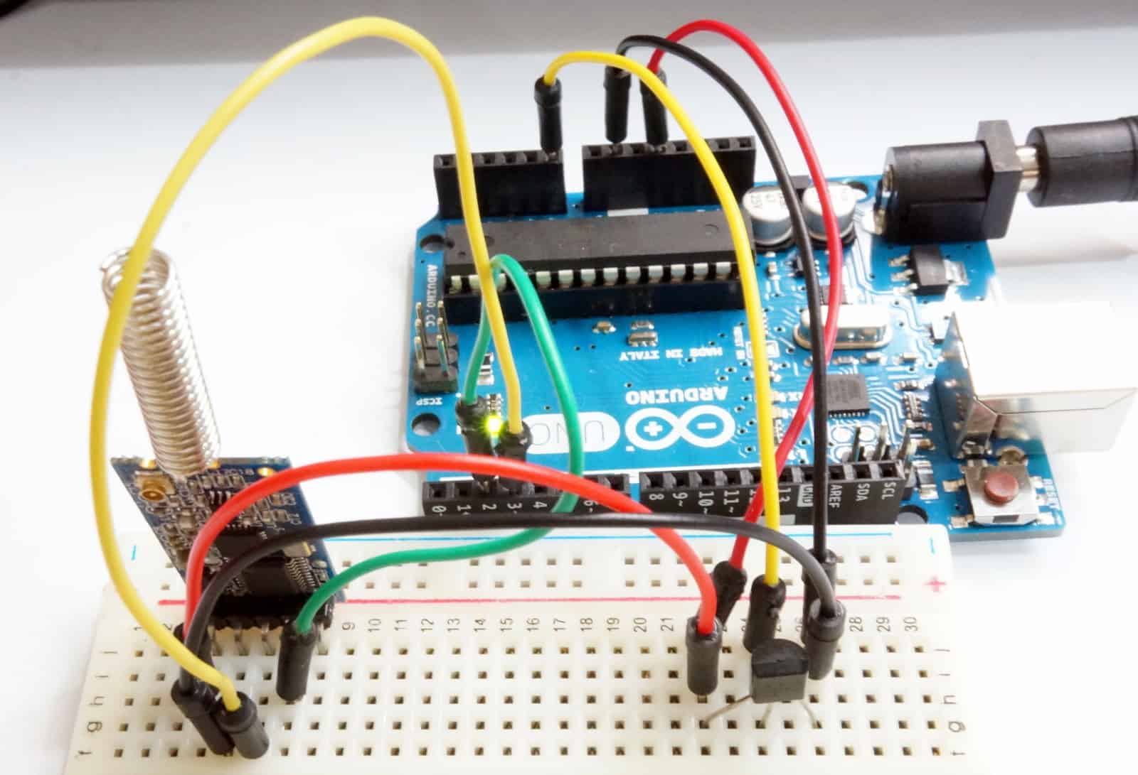
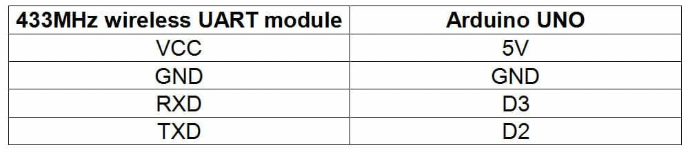
Arduino with 434MHz (100 meters) Wireless UART, please make the following connection. The pin assignments for the wireless UART module are labeled at the back of the module.
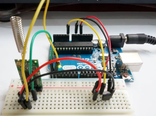
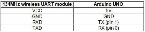
Bear in mind, the UART pins are cross-connected; the RX of Arduino should be connected to the TXD of the wireless module and vice versa for the TX of Arduino.
How about the connection to the Computer? We will need to set up the connection for the computer to receive wireless data. I am using UC00A to receive UART data and display it in an Arduino Serial monitor, if this is your 1st time using UC00A, please refer to the User’s Manual, you will need to install the driver.
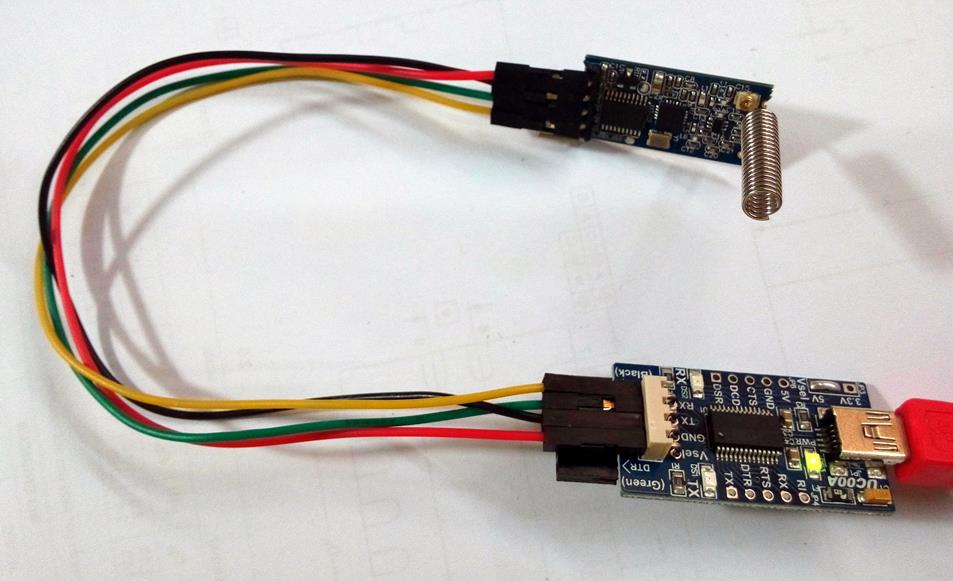
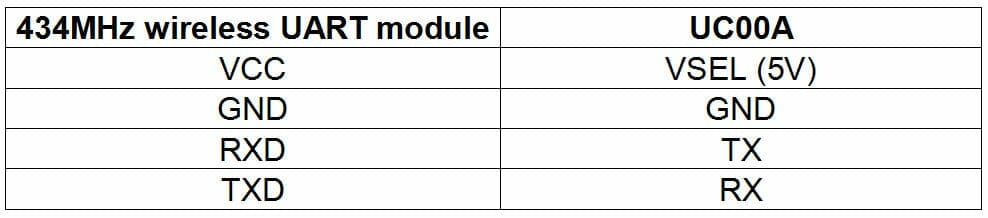
Here is a closer photo of the connections, hopefully, you can get it right. Please do not connect the supply of 5V wrongly. You will definitely damage it. The photo shows the connection to the 433MHz (1KM) module, but actually, the connections to UC00A are the same for both the 433MHz and 434MHz modules.
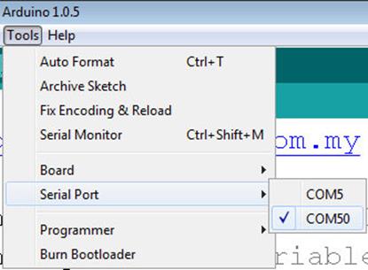
OK, good! We are done with the wiring. Now, go to Arduino IDE, and close the Serial Monitor. Choose a different COM number for the Serial port. We are not going to load any program here. Just choose the com port UC00A connected to. Go to Tools -> Serial Port -> Choose the new com number. Previously my Arduino UNO is COM 5, after I connect UC00A and install the driver, I have another new COM port which is 50. You should check the COM port number for your UC00A. It can be any number.
Now open the Serial Monitor again. Notice the temperature is being updated through the new com port? Wireless via the 434MHz wireless module. Oh, is getting hot here!
Good! You get it, hopefully! If you cannot get it, please check the connection again, most likely is due to the wrong connection! Not to forget to try sending ‘a’ or ‘A’ to control the LED on Arduino.
433MHZ (1KM) WIRELESS UART MODULE, MODIFICATION NEEDED
Now, allow me to show the modification needed if you want to use a 433MHz (1km) wireless UART module.
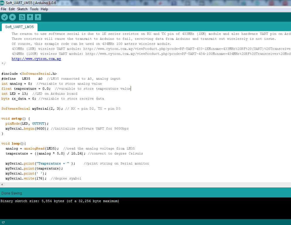
1st, after you verify the LM35 temperature monitoring and control with a USB connection. You will need to load this sketch (Soft_UART_LM35) which uses the software UART to send and receive data.
And changes on the connection from Arduino to the 433MHz module.
Do take note of the pins from Arduino for the UART shift from D0 to D2, and D1 to D3. We are utilizing software serial to transmit and receive data. The connection of the 433MHz module to UC00A is the same as the connection of 434MHz. Choose the correct COM port and open the serial monitor from Arduino IDE. You should get the same result.
These modifications are needed due to the 1K series resistor on 433MHz and Arduino TX and RX pin. If you are using PIC or other types of microcontroller, this modification might not be needed.
SUMMARY
If you study the tutorial and try it out, you will notice you did not modify the code if you are using a 434MHz (100 meters) wireless module. Even if you use a 433MHz (1km) wireless UART module, the modification is minor only. Yes, it is easy and straightforward to use. BTW, it is bidirectional communication, but in half duplex mode. You can still control LEDs, outputs, or motors on Arduino, but please develop a program to do so. Good luck!
I will explain how to configure the module in another topic.
If you have any inquiries, please do post in our technical forum as we seldom visit the comments section under the tutorial page.
Attachment:
There are two folders in this repository:
- UART_LM35 – Hardware UART LM35 temperature monitor and control (434MHz only)
- Soft_UART_LM35 – Software UART LM35 temperature monitor and control (433MHz and 434MHz)